

Download Data Sheet
×
Options for Downloading the Data Sheet
By sharing your email, you grant SantEnt the right to store your email and use it for communication purposes if required. We won't spam you.
Description
Brand - RINGSPANN
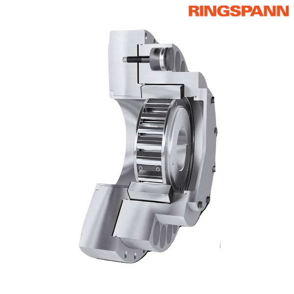
Part Number - FXRW 120 - 50 MX RINGSPANN
Category - Integrated Freewheels FXRW
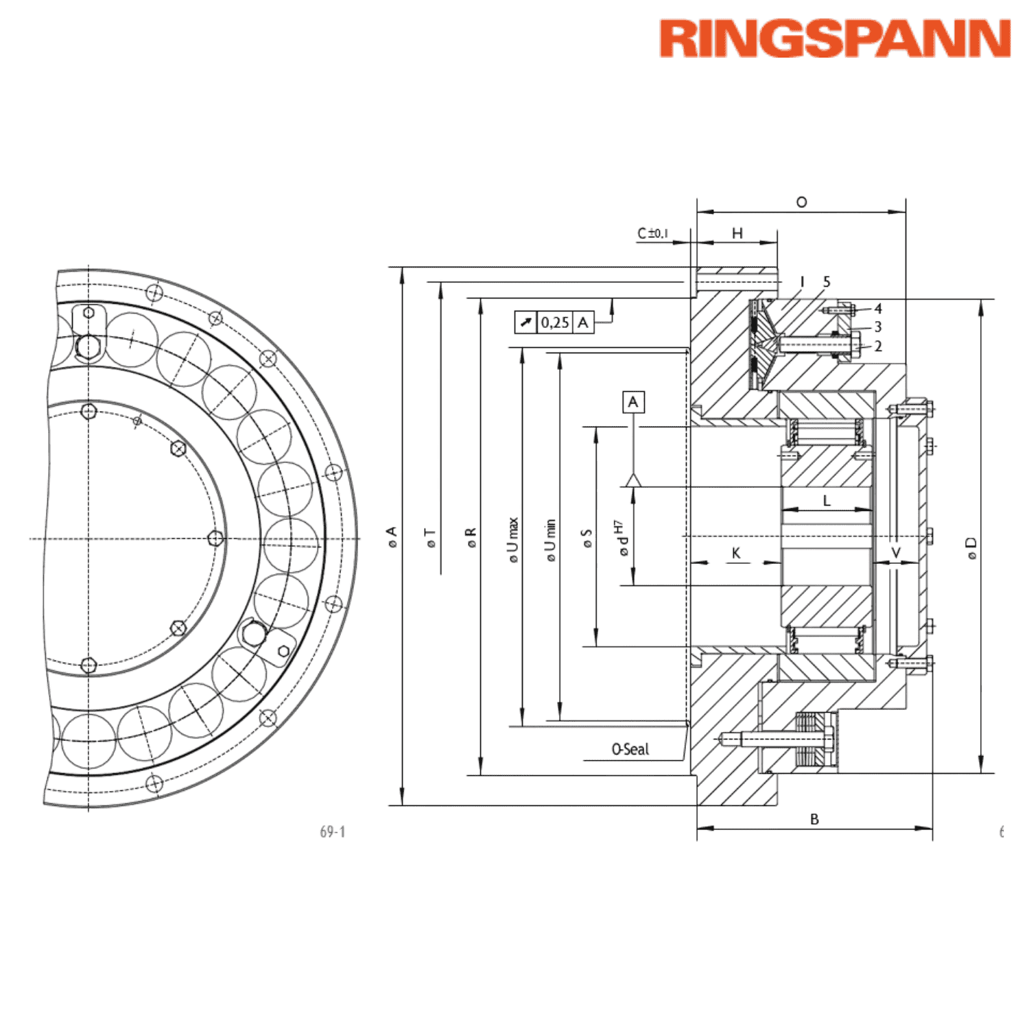
Principal Dimensions & Specifications (Metric):
Maximum Bore Diameter (d) - 95 mm
Dimension (A) - 400 mm
Dimension (B) - 192 mm
Dimension (C) - 6 mm
Dimension (D) - 345 mm
Thread (G) ** - M 16
Dimension (H) - 69 mm
Dimension (K) - 77.5 mm
Dimension (L) - 70 mm
Dimension (O) - 167 mm
Dimension (R) - 340 mm
Dimension (S) - 145 mm
Dimension (T) - 373 mm
Minimum Dimension (U) *** - 200 mm
Maximum Dimension (U) *** - 260 mm
Dimension (V) - 34 mm
Number of Fastening Holes (Z) ** - 6
Weight - 101 kg
Slipping Torque (MR) - 7300 Nm
Sprag Lift-off at Inner Ring Speed - 320 RPM
Maximum Speed of Inner Ring Freewheels - 4000 RPM
Other salient points to be noted:
* Keyway according to DIN 6885
** Z = Number of fastening holes for screws G on pitch circle T
*** Area for O-ring sealing
Features:
• Integrated Freewheels FXR are sprag-type freewheels without built-in bearing support, featuring sprag lift-off design (X)
• They are based on the FXM series (refer to pages 58–63) but include an additional integrated torque limiter
• The sprag lift-off mechanism ensures no contact during high-speed inner ring rotation, resulting in wear-free operation
• Upon stoppage, the full backdriving torque often gets concentrated on a single backstop, which can overload it
Application as: Backstop (For continuous conveyor systems that use multiple drives, each fitted with its own backstop)
Torques:
• Integrated Freewheels FXRW come with a factory-set slipping torque value (MR) in the torque limiter
• The system’s static backdriving torque (ML), including during overload, must never exceed the combined MR values of all FXRW freewheels used
• The MR values listed in technical tables represent maximum permissible limits
Mounting:
• Integrated Freewheels FXRW do not include internal bearing support
• Total Indicated Runout (T.I.R.) between the pilot diameter (R) and shaft diameter (d) must not exceed 0.25 mm
• Dimension C refers to the freewheel's centering depth; the customer’s attachment part must have a minimum centering depth of C + 0.2 mm
• Pilot diameter (R) of the attachment part must be to ISO H7 tolerance
• Shaft diameter must be to ISO h6 or j6 tolerance
♦ ♦ Images are for representation purposes only
Part Number - FXRW 120 - 50 MX RINGSPANN
Category - Integrated Freewheels FXRW
Principal Dimensions & Specifications (Metric):
Maximum Bore Diameter (d) - 95 mm
Dimension (A) - 400 mm
Dimension (B) - 192 mm
Dimension (C) - 6 mm
Dimension (D) - 345 mm
Thread (G) ** - M 16
Dimension (H) - 69 mm
Dimension (K) - 77.5 mm
Dimension (L) - 70 mm
Dimension (O) - 167 mm
Dimension (R) - 340 mm
Dimension (S) - 145 mm
Dimension (T) - 373 mm
Minimum Dimension (U) *** - 200 mm
Maximum Dimension (U) *** - 260 mm
Dimension (V) - 34 mm
Number of Fastening Holes (Z) ** - 6
Weight - 101 kg
Slipping Torque (MR) - 7300 Nm
Sprag Lift-off at Inner Ring Speed - 320 RPM
Maximum Speed of Inner Ring Freewheels - 4000 RPM
Other salient points to be noted:
* Keyway according to DIN 6885
** Z = Number of fastening holes for screws G on pitch circle T
*** Area for O-ring sealing
Features:
• Integrated Freewheels FXR are sprag-type freewheels without built-in bearing support, featuring sprag lift-off design (X)
• They are based on the FXM series (refer to pages 58–63) but include an additional integrated torque limiter
• The sprag lift-off mechanism ensures no contact during high-speed inner ring rotation, resulting in wear-free operation
• Upon stoppage, the full backdriving torque often gets concentrated on a single backstop, which can overload it
Application as: Backstop (For continuous conveyor systems that use multiple drives, each fitted with its own backstop)
Torques:
• Integrated Freewheels FXRW come with a factory-set slipping torque value (MR) in the torque limiter
• The system’s static backdriving torque (ML), including during overload, must never exceed the combined MR values of all FXRW freewheels used
• The MR values listed in technical tables represent maximum permissible limits
Mounting:
• Integrated Freewheels FXRW do not include internal bearing support
• Total Indicated Runout (T.I.R.) between the pilot diameter (R) and shaft diameter (d) must not exceed 0.25 mm
• Dimension C refers to the freewheel's centering depth; the customer’s attachment part must have a minimum centering depth of C + 0.2 mm
• Pilot diameter (R) of the attachment part must be to ISO H7 tolerance
• Shaft diameter must be to ISO h6 or j6 tolerance
♦ ♦ Images are for representation purposes only
Download Data Sheet
×
Options for Downloading the Data Sheet
By sharing your email, you grant SantEnt the right to store your email and use it for communication purposes if required. We won't spam you.
