


Download Data Sheet
×
Options for Downloading the Data Sheet
By sharing your email, you grant SantEnt the right to store your email and use it for communication purposes if required. We won't spam you.
Description
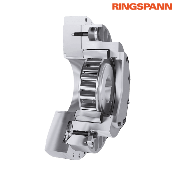
Brand - RINGSPANN
Part Number - FXRU 290 - 96 LX RINGSPANN
Category - Integrated Freewheels FXRU
Principal Dimensions & Specifications (Metric):
Maximum Bore Diameter (d) - 230 mm
Dimension (A) - 850 mm
Dimension (B) - 340 mm
Dimension (C) - 8 mm
Dimension (D) - 735 mm
Thread (G) ** - M 24
Dimension (H) - 127 mm
Dimension (K) - 140 mm
Dimension (L) - 120 mm
Dimension (O) - 302 mm
Dimension (R) - 730 mm
Dimension (S) - 330 mm
Dimension (T) - 800 mm
Minimum Dimension (U) *** - 405 mm
Maximum Dimension (U) *** - 730 mm
Dimension (V) - 65 mm
Number of Fastening Holes (Z) ** - 12 mm
Weight - 853 kg
Slipping Toeque (MR) - 90000 Nm
Sprag Lift-off at Inner Ring Speed - 200 RPM
Maximum Speed Inner Ring Freewheels - 2250 RPM
Other salient points to be noted:
* Keyway according to DIN 6885
** Z = Number of fastening holes for screws G on pitch circle T
*** Area for O-ring sealing
Features:
• Integrated Freewheels FXR are sprag-type freewheels without built-in bearing support, featuring sprag lift-off design (X)
• The sprag lift-off mechanism ensures no contact during high-speed inner ring rotation, resulting in wear-free operation
• Upon stoppage, the full backdriving torque often gets concentrated on a single backstop, which can overload it
Application as: Backstop (For continuous conveyor systems that use multiple drives, each fitted with its own backstop)
Torques:
• IIntegrated Freewheels FXRU are equipped with a preset slipping torque (MR) for the built-in torque limiter
• The static backdriving torque (ML) of the installation, even under overload conditions — must never exceed the combined MR values of all installed freewheels
Mounting:
• Integrated Freewheels FXRU do not have bearing support
• The runout (T.I.R.) between the pilot diameter (R) and shaft diameter (d) must not exceed 0.25 mm
• Dimension C is the reference depth for the freewheel installation
• The centering depth of the customer’s attachment part must be at least C + 0.2 mm
• The pilot diameter R must have a tolerance of ISO H7
• The shaft diameter must conform to ISO h6 or j6 tolerance
♦ ♦ Images are for representation purposes only
Download Data Sheet
×
Options for Downloading the Data Sheet
By sharing your email, you grant SantEnt the right to store your email and use it for communication purposes if required. We won't spam you.
