

Download Data Sheet
×
Options for Downloading the Data Sheet
By sharing your email, you grant SantEnt the right to store your email and use it for communication purposes if required. We won't spam you.
Description
Brand - RINGSPANN
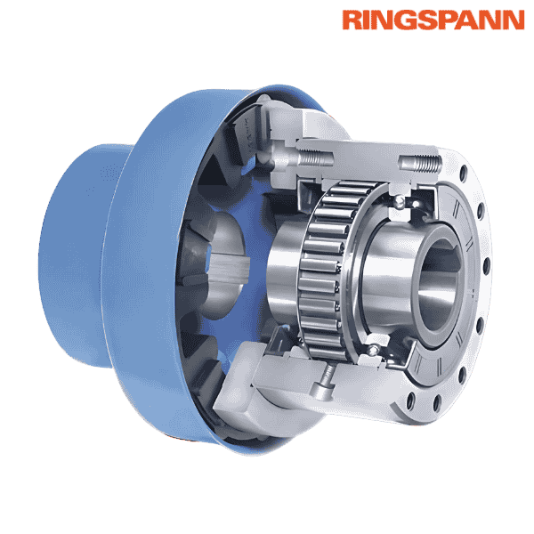
Part Number - FBE 200 SFT RINGSPANN
Category - Complete Freewheels FBE
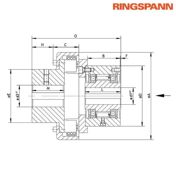
Principal Dimensions & Specifications (Metric):
Standard Bore Diameter (d1) - 120 mm
Maximum Bore Diameter (d1) - 120 mm
Standard Bore Diameter (d3) - 120 mm
Minimum Bore Diameter (d3) - 85 mm
Maximum Bore Diameter (d3) - 160 mm
Dimension (A) - 432 mm
Dimension (B) - 143 mm
Dimension (C) - 141 mm
Dimension (D) - 300 mm
Dimension (E) - 255 mm
Dimension (F) - 5 mm
Dimension (H) - 104 mm
Dimension (L) - 160 mm
Dimension (M) - 160 mm
Dimension (O) - 408 mm
Weight - 11.6 kg
Type - Type with RIDUVIT® For Extended Service Life with Coated Sprags (SFT)
Nominal Torque (MN) - 20000 Nm
Maximum Speed of Inner Ring Overruns - 630 RPM
Maximum Speed of Outer Ring Overruns - 900 RPM
Description of Suffix:
SFT - Type with RIDUVIT® For Extended Service Life with Coated Sprags
Other salient points to be noted:
• The maximum transmissible torque is 2 times the specified nominal torque
• For bore d1: Keyway according to DIN 6885
• For bore d1: Keyway width tolerance JS10
• For bore d3: Keyway according to DIN 6885
• For bore d3: Keyway width tolerance P9
Features:
• Handles nominal torques up to 160,000 Nm
• Available with bores up to 300 mm; many standard bore sizes readily available
Application as: Overrunning Clutch
Application Example:
• Two Complete Freewheels FBE 72 with shaft coupling are used as overrunning clutches in the drive unit of a tube mill with an auxiliary drive
• A standard FBE 72 SF (Freewheel 1) is installed between the main drive and the angular gear
• A FBE 72 LZ (Freewheel 2), equipped with sprag lift-off Z, is installed between the auxiliary drive and the angular gear
• In auxiliary power mode, the auxiliary drive powers the system through Freewheel 2 (driving mode), while Freewheel 1 operates in freewheeling mode at low speed
• In main motor mode, the system is powered via Freewheel 1 (driving mode), while Freewheel 2 automatically overruns and disengages the auxiliary drive (freewheeling mode)
• The sprag lift-off Z type in Freewheel 2 allows for contact-free, wear-free operation at high speed during freewheeling
Mounting:
• The shaft coupling can be installed on either the right or left side of the freewheel, depending on the required freewheeling direction
• The shaft tolerance must comply with ISO h6 or j6
♦ ♦ Images are for representation purposes only
Part Number - FBE 200 SFT RINGSPANN
Category - Complete Freewheels FBE
Principal Dimensions & Specifications (Metric):
Standard Bore Diameter (d1) - 120 mm
Maximum Bore Diameter (d1) - 120 mm
Standard Bore Diameter (d3) - 120 mm
Minimum Bore Diameter (d3) - 85 mm
Maximum Bore Diameter (d3) - 160 mm
Dimension (A) - 432 mm
Dimension (B) - 143 mm
Dimension (C) - 141 mm
Dimension (D) - 300 mm
Dimension (E) - 255 mm
Dimension (F) - 5 mm
Dimension (H) - 104 mm
Dimension (L) - 160 mm
Dimension (M) - 160 mm
Dimension (O) - 408 mm
Weight - 11.6 kg
Type - Type with RIDUVIT® For Extended Service Life with Coated Sprags (SFT)
Nominal Torque (MN) - 20000 Nm
Maximum Speed of Inner Ring Overruns - 630 RPM
Maximum Speed of Outer Ring Overruns - 900 RPM
Description of Suffix:
SFT - Type with RIDUVIT® For Extended Service Life with Coated Sprags
Other salient points to be noted:
• The maximum transmissible torque is 2 times the specified nominal torque
• For bore d1: Keyway according to DIN 6885
• For bore d1: Keyway width tolerance JS10
• For bore d3: Keyway according to DIN 6885
• For bore d3: Keyway width tolerance P9
Features:
• Handles nominal torques up to 160,000 Nm
• Available with bores up to 300 mm; many standard bore sizes readily available
Application as: Overrunning Clutch
Application Example:
• Two Complete Freewheels FBE 72 with shaft coupling are used as overrunning clutches in the drive unit of a tube mill with an auxiliary drive
• A standard FBE 72 SF (Freewheel 1) is installed between the main drive and the angular gear
• A FBE 72 LZ (Freewheel 2), equipped with sprag lift-off Z, is installed between the auxiliary drive and the angular gear
• In auxiliary power mode, the auxiliary drive powers the system through Freewheel 2 (driving mode), while Freewheel 1 operates in freewheeling mode at low speed
• In main motor mode, the system is powered via Freewheel 1 (driving mode), while Freewheel 2 automatically overruns and disengages the auxiliary drive (freewheeling mode)
• The sprag lift-off Z type in Freewheel 2 allows for contact-free, wear-free operation at high speed during freewheeling
Mounting:
• The shaft coupling can be installed on either the right or left side of the freewheel, depending on the required freewheeling direction
• The shaft tolerance must comply with ISO h6 or j6
♦ ♦ Images are for representation purposes only
Download Data Sheet
×
Options for Downloading the Data Sheet
By sharing your email, you grant SantEnt the right to store your email and use it for communication purposes if required. We won't spam you.
